In this article, we will discuss what IR drop is in ASIC design, why IR drop problems occur, what are the effects of IR drop, and how to analyze and prevent IR drop problems.
What is the IR drop problem:
I in IR refers to current, R refers to resistance, and their multiplication is voltage. So IR drop is the voltage drop.
In layman's terms,Voltage drop refers to the voltage consumed from the chip source to the instance., for flipchip package form, it is the voltage drop from bump to instance PG pin. The actual voltage obtained by Instance is the supply voltage minus the voltage drop. For example, the external input voltage connected to the bump is Vdd 5V and Vss 0V. After the voltage of the bump reaches a certain instance, Vdd may only be 4V and Vss becomes 1V. Then the voltage obtained by this instance will be only 3V, and the voltage drop will be 2V. IR drop is an important part of the chip back-end signoff. It must be ensured that the IR drop cannot be too large, otherwise the chip may cause logic errors or stop working because it cannot obtain the required voltage. This IR drop will also have corresponding spec requirements, which are generally determined as a percentage of the supply voltage. If it is set at 10%, for a 5V input, the IR drop is required not to be greater than 0.5V.
In theory, the power supply (VDD and VSS) in the chip is evenly distributed through metal rails and stripes, which is called the power delivery network (PDN) or power grid. Each metal layer used in PDN has a finite resistivity. As current flows through the power delivery network, a portion of the applied voltage will be reduced in the PDN according to Ohm's law. Figure 1 shows the IR voltage drop in the power supply network. Any metal mesh can be assumed to be a combination of small R and C.
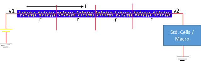
Figure 1 IR voltage drop in metal mesh
If the resistivity of the metal conductors is high or the amount of current passing through the power network is large, a large amount of voltage may be dropped in the power delivery network, resulting in less available voltage for a standard unit than the actual amount of voltage applied. If a voltage V1 is applied at the power port and a current I flows in a particular net with a total resistance R, the voltage available at the other end of the standard cell (V2) will be
Due to IR drops in the power delivery network, sometimes a standard cell or macro cell cannot get the minimum operating voltage required to make it operate, even if sufficient voltage is applied at the power port. The voltage drop in the power delivery network before reaching the standard unit is called IR drop.
This degradation can lead to poor chip performance because of the increased latency of the standard cells, which can lead to malfunctioning of the chip, creating setup/hold time violations. To avoid this problem, IR analysis must be performed and its impact in timing analysis considered during the design cycle.
Type of IR drop
There are two types of IR drops in ASIC designs:
- Static IR drop
- Dynamic IR drop
Static IR drop
Static IR drop is the voltage drop in the power delivery network (PDN) when there is no input switching (i.e. the circuit is in the static phase). The main cause of the static IR drop phenomenon is the voltage division of the metal connections of the power network, which is caused by the voltage division of the metal connections' own resistance. SoStatic IR drop is mainly related to the structure and wiring details of the power network. Therefore, static IR drop mainly considers the resistance effect and just analyzes the impact of resistance. The calculation of static voltage drop does not consider the change of current with time, or the average current over a long period of time refers to the current of the instance.
The calculation of the R value is also relatively simple. It does not consider too much the impact of the current skin effect on the resistance. It mainly considers the structure and wiring details of the power network. The R value can be extracted by the PG network and considered to be constant.
In this way, the static voltage drop obtained by multiplying the IR is also an invariant. The significance of calculating the static voltage drop is that it can quickly evaluate the PG network of the chip and whether the powerplan is good enough. If there are many static IR violations, the PG network may need to be readjusted. So, how is the average current of static IR obtained? In fact, we first use power calculation tools such as primepower to calculate the power value of the instance, and then calculate the current flowing through it based on the power and the resistance of the instance.
Dynamic IR drop
Dynamic IR drop, on the other hand, refers to the voltage drop in the power delivery network caused by current fluctuations when the input is continuously switching (i.e. when the circuit is in a functional state). Dynamic IR drop is the voltage drop caused by current fluctuations when the power supply switches on and off in the circuit. This phenomenon occurs at the triggering edge of the clock. The clock edge jump not only brings about a large number of transistor switches of its own, but also brings about the jump of the combinational logic circuit, which often generates a large current on the entire chip in a short period of time. This instantaneous large current causes the IR drop phenomenon. The more transistors that are switched at the same time, the easier it is to trigger the dynamic IR drop phenomenon.
Dynamic IR drop depends on the switching rate of the instance. The calculation of Dynamic IR is relatively complex. It takes into account the change of current with time. Through long-term simulation of the chip, it can be considered that the current of a certain instance changes periodically with time, and correspondingly its IR drop will also be a function that changes with time.
Generally, there are three indicators of concern: peak IR, average IR, and RMS IR. Peak IR is the peak voltage drop, and we need to ensure that the peak voltage drop is also within the acceptable range. Average IR refers to the average voltage drop per cycle. In fact, it is somewhat similar to static IR, but the calculation method will be different. RMS IR refers to the root mean squre IR, which is the variance of the IR drop changing over time. Sometimes we need to ensure that the voltage drop of the instance changes smoothly. RMS can reflect the discreteness of the voltage drop over time. Generally speaking, the calculation of dynamic IR takes a long time and is suitable for finding the violation of individual instances and then adjusting an instance in a targeted manner. You can move its position to an area with better IR, or you can add some PG mesh in a specific area.
When the input switches continuously, more current flows in the instance and more current flows in the PDN. Therefore, there will be more IR drop in the PDN. Therefore, dynamic IR drop is greater than static IR drop.
Causes of IR voltage drop
IR voltage drop can occur for a variety of reasons, but some of the main ones are:
- Poorly designed power delivery network (small metal width, large spacing between power strips)
- Insufficient number of vias in the power delivery network
- Insufficient number of decoupling capacitor cells (DeCap Cells)
- High cell density and high switching in specific areas
- High impedance of power delivery network
- Burst current
- Insufficient number of voltage sources
- High RC values of metal layers used to create power delivery networks
Effect of IR drop
The latency of a standard unit depends on the power available to the unit, if the power supply is reduced the latency of the unit increases. Increased cell latency can impact the performance of your design. If the available voltage of a standard unit drops below a certain level, the unit may stop functioning completely, causing functional failure of the design. Or sometimes, the IR drop will only increase the delay of the unit within the limits, thus affecting the setup and hold times of the design, and sometimes causing setup time and hold time violations. For setup violations, the frequency can be increased by increasing the voltage, but the cost is increased power consumption, and if the dynamic IR drop is not robust enough, the space for improvement in the setup may be limited by increasing the voltage. Once a hold violation occurs, the chip will not work properly. Therefore, in advanced processes, the impact of IR drop is particularly large and requires everyone's attention.
The VDD line may also drop suddenly if there is a sudden increase in current demand due to heavy switching activity in a particular area. This type of VDD level drop is calledvoltage drop. or may cause a sudden increase in ground voltage levels, known asbouncing. These are collectively referred to asPower supply noise. Figure 2 shows power supply noise due to IR drop.
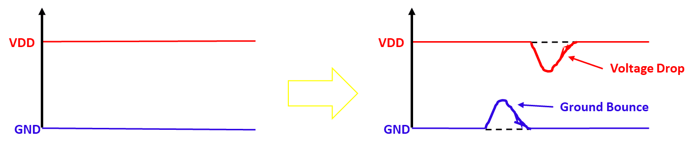
Figure 2 Power supply noise due to IR drop
In short, IR drop can cause:
- Changes in unit latency
- Possible violation of setup and hold times
- Introducing power supply noise into the power network
IR analysis and repair:
Each EDA company has its own IR analysis tool that performs IR analysis and applies IR repair techniques based on the analysis. The two most popular IR analysis tools used in industry are:
- RedHawk for Ansys
- Voltus by Cadence Design System
Depending on the analysis, various techniques to repair IR drop are applied. Some remediation measures commonly performed include:
- Insert a sufficient number of DeCap Cells to enhance the power delivery network.
- If the power delivery network is not constructed correctly, rebuild the power delivery network. We can increase the width of the metal stripes or decrease the spacing between them.
- We can scale logical units within a region so that the load can be distributed.
For more information on decoupling capacitor units, see Part 5, Section 4.
thank you
[1] https://teamvlsi.com/2020/07/ir-analysis-in-asic-design-effects-and.html
[2] https://zhuanlan.zhihu.com/p/450521738
[3] https://zhuanlan.zhihu.com/p/544002432