1. Problem background
Chips play a key role in electronic devices such as mobile phones, computers, and automobiles. The timing performance of the chip controls the data transmission speed and instruction execution time, ensuring the efficient operation of the device and the smooth user experience. This question is aimed at the performance requirements of chip design and focuses on incrementally reducing chip latency.
Timing optimization has always been an important issue in chip design. With the continuous improvement of chip integration, timing issues have become more and more complex and critical. The core of the timing optimization problem is how to reduce the chip delay to ensure the normal operation of the chip. Common techniques for timing optimization without changing the netlist include gate sizing and cell movement. Tradeoff the load capacitance of the unit's upstream and downstream to achieve latency reduction.
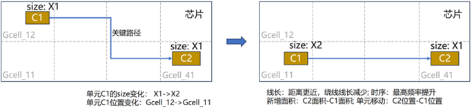
Gate sizing techniques can reduce delays along circuit paths by adjusting the size of logic gates. Specifically, increasing the gate size can drive larger loads, thereby reducing downstream latency. However, the increased gate size will cause the load on its driving unit to increase, thereby increasing the upstream delay; cell movement technology can improve circuit performance by rearranging the logic cells in the circuit. By placing related units close to each other, circuit path lengths can be reduced and latency reduced.
This question focuses on the distribution and routing of cells after layout, and uses techniques such as gate size adjustment and cell movement to perform incremental timing optimization without changing the netlist. The participating teams are required to select appropriate algorithms and use parallel and other performance optimization methods as much as possible to provide high-performance timing optimization algorithms.
2. Problem description
2.1 Description
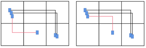
In this problem, in order to simplify the problem, the chip area is divided into grids, and the coordinates and overlap of the cells in the grid are ignored. It is only necessary that the total area of the cells in the grid does not exceed the specified maximum accommodation area. Similarly, when using a grid as a GCell, only two-dimensional wiring needs to be considered to ensure that the wire network is connected and that the wiring in each GCell does not exceed the specified wiring capacity. As shown in Figure 1.
The participating teams need to combine their understanding of timing optimization methods to design a C++ program. The program should be able to construct an appropriate data structure based on the analyzed data provided by the problem co-constructor, and complete the optimization of the layout through the timing optimization algorithm. The program output is the optimized placement and routing results. Figure 2 gives a simple example.
With the help of open source projects, the problem co-constructor provides reference processes and file analysis, as shown in Figure 3 (the yellow part needs to be filled in and designed by the participating teams). The participating teams need to complete the following points:
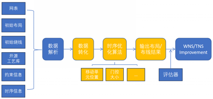
(1) Construct an appropriate data structure based on the parsed data provided by the problem co-constructor, taking into account both efficient storage and algorithm application.
(2) For the unit layout, it is required to optimize without changing the netlist. The gate size adjustment will provide a standard unit library. The unit library provides n sizes for the logic units of each function, that is, there are n different library units that implement the same combinational logic function. In order to ensure that the optimized netlist maintains its original logic functions, each unit can only be replaced with a library unit with the same combinational logic function.
(3) If the wiring needs to be updated after the unit is moved, the wiring demand must be less than the wiring capacity. The wiring demand is calculated as the number of complete tracks passing through the GCell. The wiring capacity is calculated as when a line completely passes through the GCell, a complete track will be used. If it does not pass through completely, it is simply calculated as 0.5 tracks. The issue co-creator will provide samples for comparison.
(4) On the basis of meeting the constraints of increasing the area, perform timing optimization and output the legal placement and routing results after timing optimization.
(5) Use the timing evaluation tool of the problem co-builder to obtain the evaluation results. According to the routing conditions output by the participating teams, according to the line length and unit RC, the timing evaluation tool uses the nonlinear delay model (NLDM) and the interconnection line Elmore to calculate the worst/total negative margin.
This problem allows participating teams to use up to 8 threads for parallel acceleration based on the specific needs of the algorithm.
2.2 Problem Case
The problem co-creator provides the participating teams with problem cases and procedures for verifying and optimizing the design. Below is a simple example of the provided file.
(1) Netlist: netlist (.v file)
(2) Initial layout: GCell unit location information (.def file)
The specific unit descriptions are as follows:
- Cell
The unit under the corresponding process contains information such as shape (such as width, height), category tag (required for Gate Sizing), etc.
Data (information) acquisition interface:
int get_width() const; // Get the unit width
int get_height() const; // Get the height of the unit
equivCellType get_equiv_cell_type() const; // Get the category of the unit
- Instance
The unit instance used in the design file corresponds to the specific Cell; the pin points required for the connection relationship (Net) are marked, and an interface for obtaining and updating the position is provided.
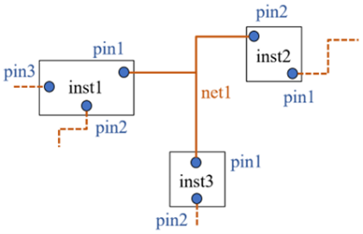
Data (information) acquisition interface
Cell get_cell() const; // Get the corresponding cell under the process
Cellint get_coordi_x() const; // Get the abscissa of the lower left corner of Instance
int get_coordi_y() const; // Get the ordinate of the lower left corner of Instance
void update_location(Point);
global interface
vector `<Instance>` get_inst_list() const; // Get the collection of all units in the design
vector `<Net>` get_net_list() const; // Get the collection of all wire nets in the design
vector `<Cell>` obtain_equiv_cells(Cell* cur_cell); // Enter the current Cell and obtain a Cell collection of the same type (for Gate Sizing)
(3) Initial winding
- GCell
GCell is a rectangular grid. The layout is divided into multiple grids through GCell. The GCell specifications of each layer are the same, and their definition is as follows:
GCELLGRID [axis] [start] DO [scale_num] STEP [interval]
Among them, "GCELLGRID" is the starting field defined by GCell; "[axis]" is the axis direction to be described, X and Y; "[start]" is the coordinate where the axis starts; "[scale_num]" is the number of coordinates on the axis; "[interval]" is the interval between coordinates.
An example in def is as follows:
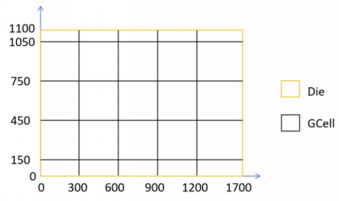
GCELLGRID X 1200 DO 2 STEP 500
GCELLGRID X 0 DO 5 STEP 300
GCELLGRID Y 1050 DO 2 STEP 50
GCELLGRID Y 150 DO 4 STEP 300
GCELLGRID Y 0 DO 2 STEP 150
The above GCellGrid definition is as follows on the layout (Die):
- Guide file
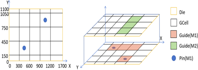
Guide is the result of routing. Its unit is a complete GCell. Guide only needs to describe the routing layer.
Taking net0 as an example, the wiring results are as follows in the guide file:
net0(
300 150 1200 450 M1
900 150 1200 1050 M2
900 750 1200 1050 M1)
The size distribution of GCell in each layer is consistent. By analyzing the guide, the wiring results of net0 are as follows:
- Open source process library (.tlef file, .lef file, .lib file)
- sdc file (.sdc file) defines the clock that needs to be optimized for timing.
2.3 Output files
This question requires the participating team's program to output the optimized unit layout and wiring results after completing timing optimization. The format of the output file should be consistent with the format input in the problem case provided by the problem co-creator.
2.4 Environment
It is recommended that participating teams use a C++ version compatible with C++20 for their development environment and operating environment, and develop under a Linux system environment. Reference methods are given below:
(1) Code download address:https://gitee.com/oscc-project/iEDA/tree/OS-Contest/
(2) Download from Dockerhub and use the compilation tools and dependent libraries provided by the image to build the project.
(3) Manually install dependencies and compile.
3. Scoring criteria
All test cases of the problem are divided into three categories: large, medium and small test cases according to the size of the netlist. Questions are screened from these three types of test cases and some cases are provided to participating teams to evaluate the quality of the algorithm; the remaining cases are only used for scoring purposes and are not open to participating teams.
Each test case has an independent score and follows the same scoring criteria:
(1) On the basis of limiting the increased area, compare the improvement of the worst/total negative margin. The larger the value, the higher the ranking. Take the top 10 teams, 10 points for the first place, 9 points for the second place, and so on.
(2) The output layout results need to meet the legality requirements (unit area within GCell, no overflow of wiring between GCells), and run under the given running time and memory limits, otherwise no points will be awarded.
(3) After scoring each case in the scoring case set, the total score is the weighted sum of the scores of individual cases, where the weight coefficient of a single case is positively related to the size of the case. The team with a higher total score will be ranked higher.