As the basic building blocks in ASIC (Application Specific Integrated Circuit) design, standard cells are well-defined and pre-characterized. They are highly reusable and can be reused in different projects or systems, thus saving a lot of ASIC design time. The concept of reusability means that a certain component, module or part of the design can be flexibly reused in multiple different scenarios, avoiding the workload and time of repeated design.
Standard cell layout
All standard cells are equal in height and vary in width. The main features of the standard unit are explained in the figure below.
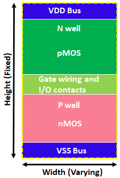
Figure 1 Standard unit layout style
In the layout of a standard cell, there are VDD power lines on the top and VSS power lines on the bottom, both drawn on the Metal 1 layer. Between the VDD power line and the VSS power line, there are three key areas, namely the n-type well area, the gap between the n-type well and the p-type well, and the p-type well area. The n-well area is close to the VDD power line, while the p-well area is close to the VSS power line. The pMOS transistors are built within the n-well, so all pMOS transistors are located in the upper half of the cell, similarly all nMOS transistors are located in the lower half of a standard cell.
The schematic layout of a standard cell can be drawn in many different ways. Taking NAND gates as an example, the layout can be designed in two different styles. One layout style is to stack two nMOS transistors on top of each other, not on the same level. Another layout style draws all nMOS transistors and pMOS transistors separately on one level. Additionally, gates in layout styles can be drawn horizontally, or nMOS and pMOS can be drawn separately.
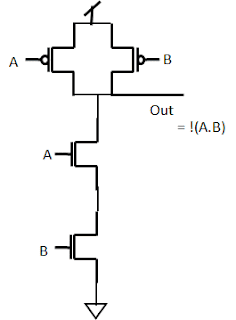
Figure 2 Schematic diagram of NAND gate
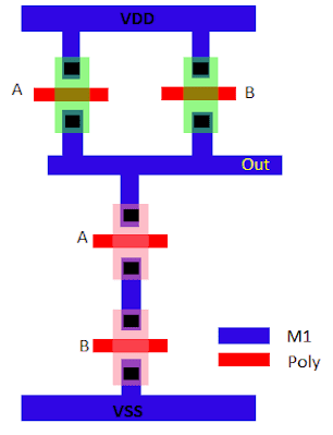
Figure 3 NAND gate layout
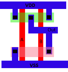
Figure 4 NAND gate layout
Figure 2 shows the schematic of a NAND gate, and Figures 3 and 4 show two different layouts of the schematic. In Figure 3, the two nMOS are not on the same level, they are stacked together, but in the layout of Figure 4, all nMOS are on one level and all pMOS are on one level. Also in Figure 3, the gates are drawn horizontally and are not shared between nMOS and pMOS. But in Figure 4, all polysilicon gates are drawn vertically and are common to both nMOS and pMOS.
Why choose a design like the second layout style? There are many reasons, here are some of them:
- Save design area: The n-type wells and p-type wells of all standard units are located at the same level, and they can be conveniently adjacent and form a shared well, thus saving a lot of area.
- Easy to arrange automatically: All standard cells have the same height and can be easily placed in standard cell rows, so autolayout tools can do the job more easily. The power cord is also located in the same location for all standard units, making power cord layout much simpler.
- Easy to wire: Standard cells have pins located at the intersection of horizontal and vertical rails, making routing easy with automated routing tools.
Tracks in standard units
There is also the concept of tracks in standard cells, which can be defined as lines drawn on a metal layer. Each track represents an M1 pitch. The height of a standard unit is usually measured by the number of tracks. For example, a 6T standard unit means that the height of the unit is 6 M1 tracks. An example is shown here, which is a standard unit with a height of 13T.
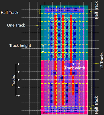
Figure 5 A standard unit with a height of 13T
In this example, the height of one orbit is 190 nanometers. Therefore, the total height of the cell is 13T = 2470 nm (13 x 190) and the width is 5T = 950 nm (5 x 190).
For standard cell libraries, there are usually a variety of options for different track heights. According to the needs of the ASIC, the standard library of the corresponding track height can be selected. There are usually three standard cell library sets, namely small transistor standard cells, large transistor standard cells and medium-sized transistor standard cells. Below are some examples showing standard units of different heights, 6T, 12T and 9T.
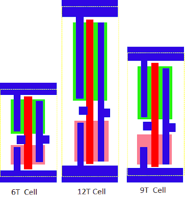
Figure 6 Standard units of different heights
Small transistor standard cells (6T) are suitable for high-density designs and have lower power consumption. They are very popular in mobile applications and ultra-low power applications, and are also widely used in embedded microcontrollers.
Large transistor standard cells (12T) take up a larger area but offer excellent performance and speed. They are used in scenarios such as high-speed computing and critical blocks to provide excellent performance.
The medium-sized transistor standard cell (9T) strikes a balance between large and small transistors to meet area requirements while maintaining performance. They are widely used in fields such as general computing, GPU and general circuits.
In actual design, we need to choose standard units of different heights according to needs and weigh the relationship between area/power consumption and performance. For better selection, we can compare their performance and area to further determine which standard unit is best suited for a specific application.
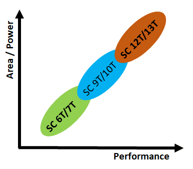
Figure 7 Performance and area trade-offs for various height standard units
Various applications of these units are as follows:
- Small transistor unit (6T unit)
- Minimal area and low power consumption
- mobile application
- Ultra-low power applications
- Embedded microcontroller
- Large transistor unit (12T unit)
- Large area occupied
- High performance and speed
- high speed computing
- critical block
- Medium Transistor Unit (9T Unit)
- Balance between area and performance
- general computing
- GPU
- Universal circuit
In short, standard cells in physical design are the basic building blocks of ASIC design and are highly reusable. Through reasonable layout and use of standard cells of different heights, we can achieve efficient and flexible chip design to meet the needs of various applications.
References
https://teamvlsi.com/2020/05/standard-cells-in-asic-design-standard-cells-in-vlsi.html