Let’s quickly understand the basic content of SDC with quick questions and answers~
1 What is an SDC file?
SDC stands for Synopsys Design Constraint, based onTCL format, developed and defined by Synopsys.
SDC is aCommon design constraint format, supported by almost all synthesis, PnR and other tools.
This file has the extension .sdc。
SDC will be used when writing constraints during logic synthesis and from synthesis to wiring.
2 What is the function of SDC file?
SDC design constraint files are used to constrain circuitsTiming, power consumption, areaetc., so that the chip meets the specifications required by the design.
3. Generation of SDC files?
SDC files can be generated by synthesis toolsLogic Synthesis tool Generate, generate after adding some constraints, and usePnR(Place and Route), that is, the layout and routing link.
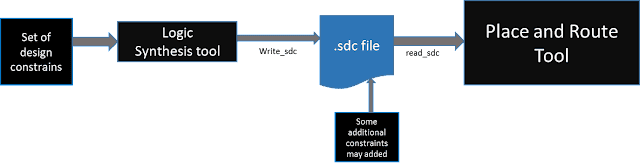
Figure 1 SDC file generation process
4 Contents of SDC files and their commands
The SDC file contains the following 4 parts: ① version; ② basic unit; ③ design constraints; ④ comment part. Among them, design constraints are the Main topics of SDC, and parts ①, ②, and ④ are not necessary.
(1) SDC version
This statement specifies the version of the SDC file. It can be 2.1, 2.0, 1.9 or earlier. Version 2.1 was introduced in December 2017.
Example:
set sdc_version 2.1
(2) Basic unit
You can use the set_unit command to specify units for various quantities, such as time, resistance, capacitance, voltage, current, and power. Multiple units can also be set using a single set_unit command.
Example:
set_units -time ns -resistance Kohm -capacitance pF -voltage V -current mA
(3) Comments section
An SDC file will contain the SDC version number at the beginning of the file, followed by the design constraints. Comments (comments starting with the character # and ending at the end of the line) can be interspersed with the design constraints in the SDC file. Longer command lines within design constraints can be split into multiple lines using the backslash (\) character.
(4) Design constraints
SDC commands related to design constraints can be divided into 9 categories, as follows:
- Work environment related commands
Work environment commands set operating_conditions Used to set the library files and working environment corresponding to the fastest and slowest conditions of the circuit.
Example:
# Define working conditions
set_operating_conditions -process "typical" -corner "slow" { voltage 1.0 temperature 25
} set_operating_conditions -process "typical" -corner "fast" { voltage 1.1 temperature 85
}
In this example, we define two different working conditions: one is in the case of a typical process and slow corner, the voltage is 1.0V and the temperature is 25 degrees Celsius; the other is in the case of a typical process and fast corner, the voltage is 1.1V and the temperature is 85 degrees Celsius.
- Commands related to design rule constraints
All commands constrained by design rules are as follows:

| serial number | Command name | Description | Example |
|---|---|---|---|
| 1 | create_clock | Define the clock signal and its characteristics. | create_clock -period 10 [get_ports clk] |
| 2 | create_generated_clock | Create a clock derived from a clock. | create_generated_clock -name Gated_Clock -source Main_Clock -divide_by 2 |
| 3 | set_clock_groups | Define clock groups. | set_clock_groups -logically_exclusive {Group1 Group2} |
| 4 | derived_clock | Create a derived clock. | derived_clock -source Parent_Clock -divide_by 4 |
| 5 | set_clock_latency | Set the delay of the clock path. | set_clock_latency -source Main_Clock -max 5 [get_pins DFF*] |
| 6 | set_input_delay | Set input delay. | set_input_delay 2 -clock [get_clocks Main_Clock] [get_ports data_in] |
| 7 | set_output_delay | Set output delay. | set_output_delay 1 -clock [get_clocks Main_Clock] [get_ports data_out] |
| 8 | set_max_delay | Set the maximum delay for the path. | set_max_delay 6 -from [get_pins U1/Q] -to [get_pins U2/D] |
| 9 | set_min_delay | Set the minimum delay for the path. | set_min_delay 2 -from [get_pins U1/Q] -to [get_pins U2/D] |
| 10 | set_false_path | Specify paths that do not require timing verification. | set_false_path -from [get_pins U1/Q] -to [get_pins U2/D] |
| 11 | set_multicycle_path | Set up multi-cycle paths. | set_multicycle_path -setup 2 -hold 1 -from [get_pins U1/Q] -to [get_pins U2/D] |
| 12 | set_disable_timing | Disable timing analysis for a specific path. | set_disable_timing -from [get_pins U1/Q] -to [get_pins U2/D] |
| 13 | set_false_hold | Set hold time constraints. | set_false_hold -from [get_pins U1/Q] -to [get_pins U2/D] |
| 14 | set_max_fanout | Set the maximum number of loads on the path. | set_max_fanout 10 [get_nets clk_net] |
| 15 | set_max_transition | Set signal transition time. | set_max_transition 0.2 [get_pins U1/Q] |
| 16 | set_case_analysis | Define conditions and priorities when mixing logic. | set_case_analysis -priority high -case 1 {A B} -case 2 {C D} |
| 17 | set_disable_port_transition | Disable port transition time constraints. | set_disable_port_transition -port data_in |
| 18 | set_dont_touch | Specifies a unit that does nothing. | set_dont_touch [get_cells -hierarchical -filter {is_ff == 1}] |
| 19 | set_false_path_group | Specifies a group of paths that do not require timing verification. | set_false_path_group -group Group1 -from [get_cells -hierarchical -filter {is_latch == 1}] |
| 20 | set_max_area | Set the maximum area constraint. | set_max_area 1000 [get_cells -hierarchical -filter {is_comb == 1}] |
- Line load model related commands
In SDC (Synopsys Design Constraints),set_wire_load_min_block_size, set_wire_load_mode, set_wire_load_model and set_wire_load_selection_groupis the key command used to describe the line load model. Below we explain what they mean and provide some examples:
| Command name | meaning | Example |
|---|---|---|
| set_wire_load_min_block_size | This command is used to set the minimum line load block size. In actual designs, line loads will be divided into different blocks, and this command can specify the minimum block size. | set_wire_load_min_block_size 10This example command will set the minimum block size for line loads to 10. |
| set_wire_load_mode | This command is used to set the line load mode, such as setting whether the line load is global or local. | set_wire_load_mode localThis example command will set the line load mode to local. |
| set_wire_load_model | This command is used to set the line load model, that is, the model that describes the characteristics and behavior of the line load. | set_wire_load_model rc_treeThis example command will set the line load model to an RC tree model. |
| set_wire_load_selection_group | This command is used to set a specific line load selection group for grouping and managing different line loads. | set_wire_load_selection_group Group1 -members {net1 net2}This example command will create a line load selection group named Group1 and join net1 and net2 to this group. |
- System interface constraint related commands
There are six main commands related to the system interface:
| command | meaning | Example |
|---|---|---|
set_drive | Set the driving capability of the signal driver, that is, the current capability of the output signal. | set_drive(portA, strong) |
set_driving_cell | Specifying the driver type for a specific port ensures that signals are transmitted stably and accurately along the logical path. | set_driving_cell(portB, inverter) |
set_fanout_load | Set the load capacitance of the port, which represents the total capacitance of all load components connected to the port output signal. | set_fanout_load(portC, 10pF) |
set_input_transition | Set the input transition time of the port, that is, the time for the input signal to go from low level to high level or from high level to low level. | set_input_transition(portD, 0.1ns) |
set_load | Set the load value of the port, indicating the load capacitance connected to the port. | set_load(portE, 5pF) |
set_port_fanout_number | Set the fan-out number of the port, indicating the number of logic gates connected to a port. | set_port_fanout_number(portF, 4) |
The most important thing is to set the driving capability of the input port and set the capacitance value of the output terminal. The following is a detailed description:
a Set up the drive unit
Specifies the driving characteristics of an input or bidirectional port driven by a unit in the technology library. These commands associate library pins with input ports so that delay calculations can be accurately modeled.
Syntax:
set_driving_cell [-lib_cell lib_cell_name] [-library lib_name] [-rise] [-fall] [-min] [-max] [-pin pin_name] [-from_pin from_pin_name] [-dont_scale] [-no_design_rule] [-input_transition_rise rtrans] [-input_transition_fall ftrans] [-multiply_by_facrtor] [-clock clock_name] [-clock_fall] port_list
| parameters | Description | Example |
|---|---|---|
| set_driving_cell | Set the drive load, that is, specify the drive capability and load capacitance of a specific port. | |
| -lib_cell lib_cell_name | Specify the library unit name. | -lib_cell INV_X2 |
| -library lib_name | Specify the library name. | -library my_lib |
| -rise | Sets the drive capability for rising edges. | -rise |
| -fall | Sets the drive capability for falling edges. | -fall |
| -min | Specify the minimum value. | -min 0.1 |
| -max | Specify the maximum value. | -max 0.5 |
| -pin pin_name | Specify the port name. | -pin data_in |
| -from_pin from_pin_name | Specify the starting port name. | -from_pin source_out |
| -dont_scale | No scaling. | -dont_scale |
| -no_design_rule | Ignore design rules. | -no_design_rule |
| -input_transition_rise rtrans | Enter the rising transition time. | -input_transition_rise 0.2 |
| -input_transition_fall ftrans | Enter the fall transition time. | -input_transition_fall 0.3 |
| -multiply_by_facrtor | Multiply by the factor. | -multiply_by_facrtor 2 |
| -clock clock_name | Specify the clock name. | -clock clk_2x |
| -clock_fall | Set for the falling edge of the clock. | -clock_fall |
| port_list | Port list. | data_in data_out |
Example:
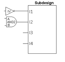
# Set the unit library to the driving unit of IV and apply it to input port I1
set_driving_cell -lib_cell IV {I1} # Set the unit library to the driver unit of AND2, and apply it to the logical path from port B to port Z, and apply it to input port I2
set_driving_cell -lib_cell AND2 -pin Z -from_pin B {I2}
b Set the load
This command sets the load attributes on the specified port and network in the current design. The units of the load value will be the capacitance units defined in the file.
Syntax:
set_load value objects [-subtract_pin_load] [-min] [-max] [[-pin_load] [-wire_load]]
Example:
# Set the pin load value to 0.001, and the target is the port named port[10]
set_load -pin_load 0.001 [get_ports {port[10]}]- Commands related to timing constraints
In this part, basically we set up clock definition, clock groups, clock delays, clock uncertainty, clock transitions, input delays, output delays, timing reductions, etc.
Create a clock
Syntax:
create_clock [-name clock_name] [clock_sources] [-period value] [-waveform edge_list] [-add] [-comment]
The create_clock command creates a clock object in the current design. This command defines the specified source_objects as clock sources.
Example: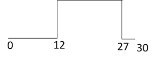
create_clock "u13/z" -name "CLK" -period 30 -waveform {12.0 27.0}`\ create_clock -name "PH12" -period 10 -waveform {0.0 5.0}
Create a generated clock
Syntax:
create_generated_clock [-name clock_name] [-add] source_objects -source master_pin [-master_clock clock] [-divide_by divide_factor | -multiply_by multiply_factor ] [-duty_cycle percent] [-invert] [-preinvert] [-edges edge_list] [-edge_shift edge_shift_list] [-combinational]
The create_generated_clock command creates a generated clock object. You can specify a pin or port as the generated clock object. The generated clock follows the master clock, so whenever the master clock changes, the generated clock automatically changes. The generated clock can be created as a frequency-divided clock, a frequency-multiplied clock, an edge-divided clock, or an inverted clock.
Example: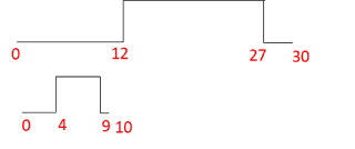
create_generated_clock -multiplied_by 3 -source CLK [get_pins div3/Q]
The above example will generate a clock derived from a raw clock named CLK. The generated clock frequency will be 3 times the original clock and the time period will be one third of the original clock (15ns –> 5ns).
group path
Syntax:
group_path [-weight weight_value] [-critical_range range_value] -default | -name group_name [-from from_list | -rise_from rise_from_list | -fall_from fall_from_list] [-through trough_list | -rise_through rise_through_list -fall_through fall_through_list] [-to to_list | -rise_to rise_to_list | -fall_to fall_to_list] [-comment comment_string] [-priority priority_level]
A group is a set of paths or endpoints used in cost function calculations. This group enables us to specify a set of paths to optimize even though there may be larger violations in other groups. When endpoints are specified, all paths leading to those endpoints are grouped.
The create_clock command will automatically create a group with a weight of 1.0 and the same name as the clock for the new clock.
Example:
group_path -name “group1” -weight 2.0 -to {CLK1A CLK1B} group_path -name GROUP1 -from [get_ports ABC/in3] -to [get-ports FF1/D]
clock uncertainty
Syntax:
set_clock_uncertainity [object_list | -from from_clock | -rise_from rise_from_clock | -fall_from fall_from_clock -to to_clock | -rise_to rise_to_clock | -fall_to fall_to_clock] [rise] [-fall] [-setup] [-hold] uncertainty
After the clocks are defined, clock uncertainty is added to handle differences in the clock network. Clock uncertainty adds some error margin to the system to account for clock network differences caused by non-idealities in the clock network and the clock source itself. The above command can specify clock-to-clock uncertainty or simple uncertainty. It sets the uncertainty to the worst-case latency expected to apply between endpoints or clock domains.
Example:
set_clock_uncertainty -setup 0.5 [get_clocks clk1]set_clock_uncertainty -hold 0.2 [get_clocks clk1]
Clock uncertainty can also be added for the rise and fall times of the clock as shown below.
set_clock_uncertainty -max_rise 0.12 [get_clocks clk1] set_clock_uncertainty -max_fall 0.12 [get_clocks clk1] set_clock_uncertainty -min_rise 0.12 [get_clocks clk1] set_clock_uncertainty -min_fall 0.12 [get_clocks clk1]
clock delay
Syntax:
set_clock_latency [-rise] [-fall] [-min] [-max] [-source] [-early] [-late] [-dynamic jitter] [-clock clock_list] delay object_list
Clock latency refers to the amount of delay in the clock signal from the clock source pin to the clock pin of the sequential element. There are two types of clock delays, network delay (default) and source delay (using the -source option).
Clock network delay is the time it takes for a clock signal to propagate from the clock definition point to the clock pin of the register. Source delay is the time it takes for a clock signal to propagate from the starting point of the actual ideal waveform to the clock definition point in the design. Source latency is also called insertion latency.
Example:
set_clock_latency 2.35 [get_pins ABC/XYZ/CP]
input lag
Syntax:
set_input_delay delay_value [-reference_pin pin_port_name] [-clock clock_name] [-level_sensitive] [-network_latency_included] [-source-latency_included] [-rise] [-fall] [-min] [-max] [-add_delay] port_pin_list
Input delay defines the timing requirements of the input port relative to the clock edge. If not specified, the input port is assumed to have zero input delay. The delay value to be specified is the delay from the starting point to the object on which set_input_delay is set relative to the clock edge.
Example:
set_input_delay -max 1.35 -clock clk1 {ain bin}
Output delay
Syntax:
set_output_delay delay_value [-reference_pin pin_port_name] [-clock clock_name] [ -clock_fall] [-level_sensitive] [-network_latency_included] [-source-latency_included] [-rise] [-fall] [-min] [-max] [-add_delay] [-group_path group_name] port_pin_list
The set_output_delay command sets the output delay requirement of the output port relative to the clock edge. If not specified, the output port is assumed to have zero output delay.
Example:
set_output_delay 1.7 -clock [get_clocks CLK1] [all_outputs]
The above command will set a 1.7 unit output delay for all output ports relative to the positive edge of CLK1 (the default edge).
set_output_delay -max 1.4 -clock {CLK} [get_ports {Y}] set_output_delay -min 1.0 -clock {CLK} [get_ports {Y}]
In the above command, the -max value refers to the longest path, and the -min value refers to the shortest path. If no -max or -min value is specified, the maximum and minimum output delays are assumed to be equal.
- Timing anomaly
In this section, some important constraints such as spurious paths, multi-cycle paths, maximum delays and minimum delays are defined.
a multi-cycle path
Syntax:
set_multicycle_path path_multiplier [-rise | -fall] [-setup | -hold] [-start | -end] [-from from_list | -rise_from rise_from_list | -fall_from fall_from_list] [-through through_list] [-rise_through rise_through_list] [-fall_through fall-through_list] [-to to_list | -rise_to rise_to_list | -fall_to fall_to_list] [-reset_path]
Multicycle paths are an exception to the default single-cycle timing requirement paths. In a multicycle path, the signal takes more than one clock cycle to propagate from the starting point to the end of the path. This command specifies the number of cycles the data path must have for a setup or hold check. The following command will set a two-cycle path constraint from source point A to end point B.
Example:
set_multicycle_path 2 -from A -to B set_multicycle_path 3 -from C
We can add a -through point between the source and end point or we can set a multi-cycle path for all paths by mentioning only the source or end point.
b pseudo path
Syntax:
set_false_path [-rise] [-fall] [-setup] [-hold] [-from from_list | -rise_from rise_from_list | -fall_from fall_from_list] [-through through_list] [-rise_through rise_through_list] [-fall_through fall-through_list] [-to to_list | -rise_to rise_to_list | -fall_to fall_to_list] [-reset_path]
A false path is a path that cannot propagate signals. For example, a path that is never activated by any combination of inputs is a false path. False paths should be disabled for timing analysis. The SDC command set_false_path is used to define false paths. False paths will be excluded from timing analysis.
Example:
set_false_path -from U1/G -to U1/D set_false_path -from {ff12} -to {ff34}
5 quotes
- "Physical Design of Digital Integrated Circuits" P239-241
- https://teamvlsi.com/2020/05/sdc-synopsys-design-constraint-file-in.html